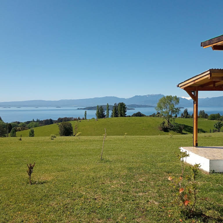
 Laguna Pitreño, Parque Futangue, Lago Ranco, Chile (-40.367191473920016, -72.31136991962883)
Ya he hablado antes de la cabaña y del lugar donde viven mis padres. En el área rural donde están no llega ningún tipo de conexión a internet por cable. Por tanto solo queda Internet móvil 4G o satelital, como Starlink.
Todas las veces que he estado ahí he trabajado con 4G, y a pesar que la conexión es buena y tiene velocidad suficiente para hacer streaming de videos, durante el día es bastante común que baje la velocidad o directamente no haya red.
Esto se vuelve especialmente irritante al usar servicios de streaming de más larga duración que requieren de una conexión estable durante al menos un par de horas, para ver el contenido. Si no se cumplen estas condiciones, nos encontramos con mucho buffering, bajadas de calidad y video pixelado. Entonces pensé que años atrás teníamos conexiones mucho peores que una conexión 4G en casa y aún así veíamos contenido (contenido libre de copyright, por supuesto).
La diferencia era en la inmediatez. Se decidía que ver, se encolaba la descarga, y se veía después tranquilamente.
Con éste principio, un servidor de segunda mano, un router 4G, Docker y algunas apps open source, se podría tener un Netflix sin conexión para cuando nuestra conexión es lenta o intermitente.
Las opciones de conexión
¿Por qué no Starlink?
Starlink tiene un valor mensual más caro y un equipo específico que se debe pagar de entrada. Unos 300€ si es reacondicionado y la mensualidad unos 45€. Creo que se justifica más si nos encontramos en una zona donde ni siquiera tenemos cobertura celular.
Operadoras rurales
Las operadoras rurales funcionan con enlaces inalámbricos a larga distancia, pero sus velocidades son menores a las de la red 4G o iguales. Pero su precio mensual es más caro que un contrato de datos móviles, por lo que tampoco se justifica. Aunque podría ser más estable, en el sentido que no se afectado por el alto trafico como la red de telefonía.
Router 4G
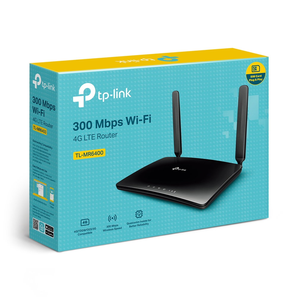
Con esta opción lo único extra fue un router 4G TP-Link TL-MR6400. Lo principal a tener en cuenta con éste tipo de dispositivo es las frecuencias en las que trabaja. La versión que compré era Europa y lo iba a instalar en otro país, por lo que las bandas pueden coincidir o no. En este caso solo una banda (banda 7) coincidió, que ya es funcional, pero hubiera estado bien haber tenido al menos una banda más de respaldo.
Existen aplicaciones para el móvil que indican a que bandas se esta conectando el teléfono, y puede servir como primera aproximación.
Mejorar la conexión con repetidores y antenas externas.
Compré también dos antenas. Un repetidor 4G y un antena multi banda externa. Ninguna de las dos dio resultado alguno y las antenas internas del router 4G probaron ser las más efectivas.
El Servidor
El ordenador que usé como servidor fue un ASUS E510 de segunda mano (80€). Las especificaciones :
- Intel i5
- 4GB RAM
- Sin Disco interno, usé un disco mecánico de 1TB (30€ segunda mano) por USB en una carcasa externa.
- La conexión al router por cable.
Aplicaciones
Ubuntu Server
Como sistema operativo, quedó ligero y arranca relativamente rápido a pesar de arrancar desde USB.
Docker
Para todas las aplicaciones instaladas y descritas aquí se usaron contenedores de Docker. Se puede seguir las instrucciones oficiales para la instalación.
Servarr
Servarr es la colección de aplicaciones encargas de automatizar la descarga de contenido y subtítulos. Se pueden agrupar y arrancar todas a la vez. Lo más importante de este fichero de configuración es que la estructura y el directorio donde se guarda todo sea el mismo y use igual para todas las aplicaciones. En este ejemplo todo esta bajo el directorio DATA, que es el mismo para todas las aplicaciones, excepto Transmission que necesitara luego un mapeo de directorio en las aplicaciones que lo usen.
version: "3.2"
services:
  radarr:
    container_name: radarr
    image: ghcr.io/hotio/radarr:latest
    restart: unless-stopped
    logging:
      driver: json-file
    ports:
      - 7878:7878
    environment:
      - PUID=1000
      - PGID=1000
      - TZ=Chile/Continental
    volumes:
      - /etc/localtime:/etc/localtime:ro
      - ./radarr/config:/config
      - "./data:/data"

  sonarr:
    container_name: sonarr
    image: ghcr.io/hotio/sonarr:latest
    restart: unless-stopped
    logging:
      driver: json-file
    ports:
      - 8989:8989
    environment:
      - PUID=1000
      - PGID=1000
      - TZ=Chile/Continental
    volumes:
      - /etc/localtime:/etc/localtime:ro
      - ./sonarr/config:/config
      - "./data:/data"

  bazarr:
    container_name: bazarr
    image: ghcr.io/hotio/bazarr:latest
    restart: unless-stopped
    logging:
      driver: json-file
    ports:
      - 6767:6767
    environment:
      - PUID=1000
      - PGID=1000
      - TZ=Chile/Continental
    volumes:
      - /etc/localtime:/etc/localtime:ro
      - ./bazarr/config:/config

      - "./data/media:/data/media"

  prowlarr:
    image: lscr.io/linuxserver/prowlarr:latest
    container_name: prowlarr
    environment:
      - PUID=1000
      - PGID=1000
      - TZ=Chile/Continental
    volumes:
      - ./prowlarr/config:/config
    ports:
      - 9696:9696
    restart: unless-stopped

  transmission:
    image: lscr.io/linuxserver/transmission:latest
    container_name: transmission
    environment:
      - PUID=1000
      - PGID=1000
      - TZ=Chile/Continental
      - TRANSMISSION_WEB_HOME= #optional
      - USER= #optional
      - PASS= #optional
      - WHITELIST= #optional
      - PEERPORT= #optional
      - HOST_WHITELIST= #optional
    volumes:
      - "./transmission-config:/config"
      - "./data/torrent/downloads:/downloads"
      - /path/to/watch/folder:/watch
    ports:
      - 9091:9091
      - 51413:51413
      - 51413:51413/udp
    restart: unless-stopped

networks:
  default:
    name: media-services
    external: true
Los servicios que se instalan con este fichero son:
- Radarr: Descarga películas
- Sonarr: Descarga de series
- Bazarr: Descarga de subtitulos
- Prowlarr: Buscador de Torrents
- Transmission: Gestor de descarga de Torrents Aquí he aprovechado para configurar que las descargan ocurran desde las 11 PM a las 6AM para liberar la red durante el dia.
Colocamos este fichero docker-compose.yml en el directorio donde queramos que se descarguen todos los archivos. Y creamos estructura de carpetas, en este caso se necesita:
/data
/data/media
/data/media/peliculas
/data/media/series
data/torrent
data/torrent/downloads
Necesitamos crear una red virtual donde estarán todos estos servicios. Lo hacemos con:
sudo docker network create media-services

```bash
Puede que no se necesite pero creo recordar que me dio errores no dar acceso a los directorios:
```bash
sudo chmod 775 -R /data
Ahora ya podemos arrancar los servicios (navegamos hasta donde esta el directorio DATA) y:
sudo docker compose up -d
Luego de esto se debe configurar cada servicio individualmente en sus respectivas paginas. Esto lo podemos hacer en un navegador en un ordenador también conectado a la red. Los pormenores de cada servicio están mucho mejor explicados en la WIKI de Servarr. https://wiki.servarr.com/
Jellyfin
Vamos a usar Jellyfin como el reproductor y para acceder y organizar toda la colección que se vaya descargando.
Creamos otro directorio donde poner el siguiente docker-compose.yml. un /jellyfin bastará.
version: '3.5'
services:
  jellyfin:
    image: jellyfin/jellyfin
    container_name: jellyfin
    network_mode: 'host'
    volumes:
      - ./config:/config
      - ./cache:/cache
      - type: bind
        source: /media/servicios-decarga-peliculas-series/data/media
        target: /media
    restart: 'unless-stopped'
    # Optional - alternative address used for autodiscovery
    environment:
      - JELLYFIN_PublishedServerUrl=http://example.com
    # Optional - may be necessary for docker healthcheck to pass if running in host network mode
    extra_hosts:
      - 'host.docker.internal:host-gateway'
Lo mas importante es el volume: source indica la ruta completa hasta el directorio donde están las película y las series. Mientras que target sera el directorio que veremos desde dentro de jellyfin cuando configuremos que carpetas son películas y que carpetas son series. Levantamos:
sudo docker compose up -d
Para configurar Jellyfin también mejor la documentación oficial https://jellyfin.org/docs/general/quick-start/ Es bastante intuitivo. El servidor estará en
http://ip_del_server:8096
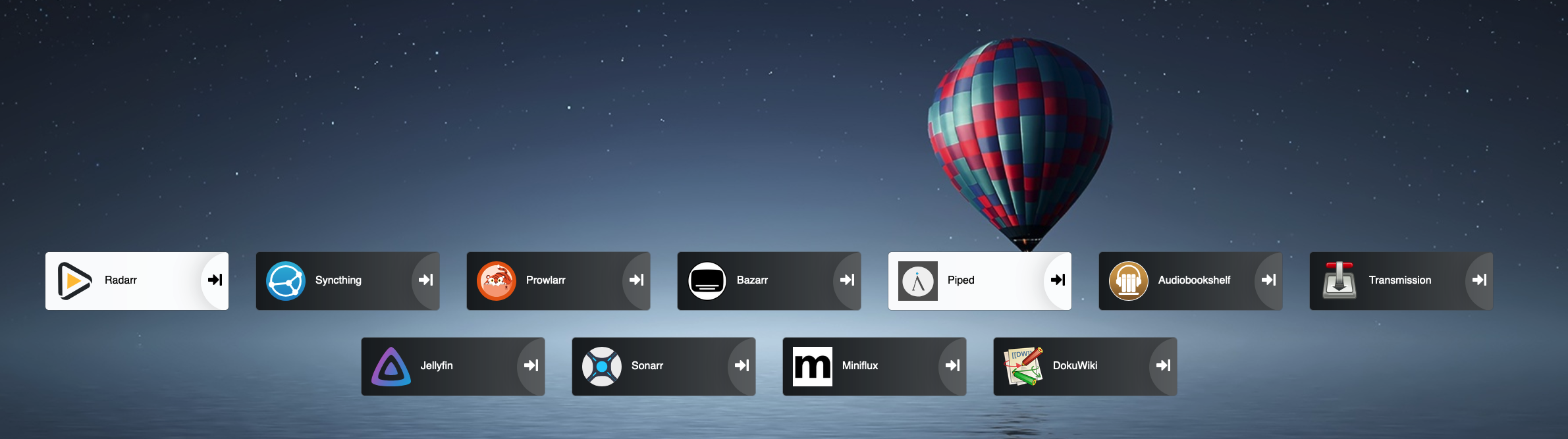
Heimdall
Heimdall nos hará las veces de portal, para poder acceder fácilmente a todos los servicios que hemos instalado.
services:
  heimdall:
    image: lscr.io/linuxserver/heimdall:latest
    container_name: heimdall
    environment:
      - PUID=1000
      - PGID=1000
      - TZ=Chile/Continental
    volumes:
      - ./config:/config
    ports:
      - 9094:80
    restart: unless-stopped
networks:
  default:
    name: media-services
    external: true
sudo docker compose up -d
Una vez levantado podremos a acceder a el con la IP_Del_server:9094 y dentro podremos ir enlazando unos a uno los servicio poniendo la IP del server y el puerto de cada uno de los servicios, estos están en la config de cada uno. También podemos poner enlaces a otros servicio con cualquier URL que nos parezcan relevantes.
Clientes
Tele
Desde la tele lo más fácil es instalar la aplicación de Jellyfin si es compatible con la tele. En mi caso son GoogleTV y la aplicación es nativa y la mayoría de contenido se puede ver directamente sin transcoding. Cuando el cliente no soporta el formato, el servidor debe transformar el contenido primero, y dependiendo de los recursos del server puede no funcionar del todo bien.
Los subtístulos también deberían estar en ficheros externos y no encapsulados dentro del archivo de video, para facilitar su visionado.
Ordenadores
Los ordenadore o cualquier dispositivo con navegador, puede entrar con la url directamente http://ipdelServer:8096
Teléfonos
Moviles y tablets pueden entrar con la app de Jellyfin.
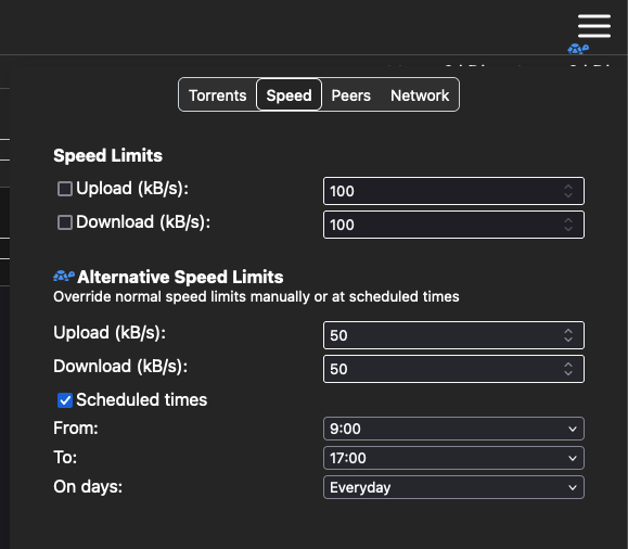
Disminuyendo tráfico
Limitar hora de descarga
Para prevenir saturar la poca conexión durante el dia se puede limitar la descarga durante el día en Transmission (http://ipDelServer:9091):
Extensiones en dispositivos
Otra manera de limitar trafico y para aprovechar al máximo la conexión es instalar un adblocker en cada dispositivo o uno a nivel de red como un piHole. Pero de eso hablaremos en otro momento.
https://adblockplus.org/
https://www.localcdn.org/
Usando RSS readers también es una manera de agilizar conexiones lentas. Para situaciones donde la conexión es mínima, se eliminar completamente JavaScript que es los que suele pesar más, a costa de que las web apps dejen de funcionar, pero útil para lectura:
https://noscript.net/getit/
Bonus: Wiki para documentación
Aprovechando la infraestructura instale una instancia de https://www.dokuwiki.org/dokuwiki
Perfecta para dejar documentado de manera sencilla algunos pasos y instrucciones del servidor.
Es fácil de instalar y los documentos se guardan también en ficheros de texto y no en base de datos.
Next steps
Usar listas de TRAKT TV
Este servició hace un seguimiento de lo que ves y puedes guardar tus listas.
Se puede configurar que una cierta lista esté conectada con el sistema de descarga para que todo lo de esa lista se descargue automáticamente. De esta manera no habría que acceder a Radarr o Sonarr en ningún momento.
También es posibles usar otras listas automáticas por ejemplo de POPULARES para tener siempre películas descargando.
Con todo esto, nos quedamos con una aceptable alternativa a la espera de la conexión por cable al lugar. Y también ya tenemos un servidor habilitado donde se podrían instalar otras aplicaciones.
Cualquier comentario o sugerencia se puede dejar en este thread del fediverso
]]>


 *this is what AI thinks of my problem


 Asi se vé ya instalada


