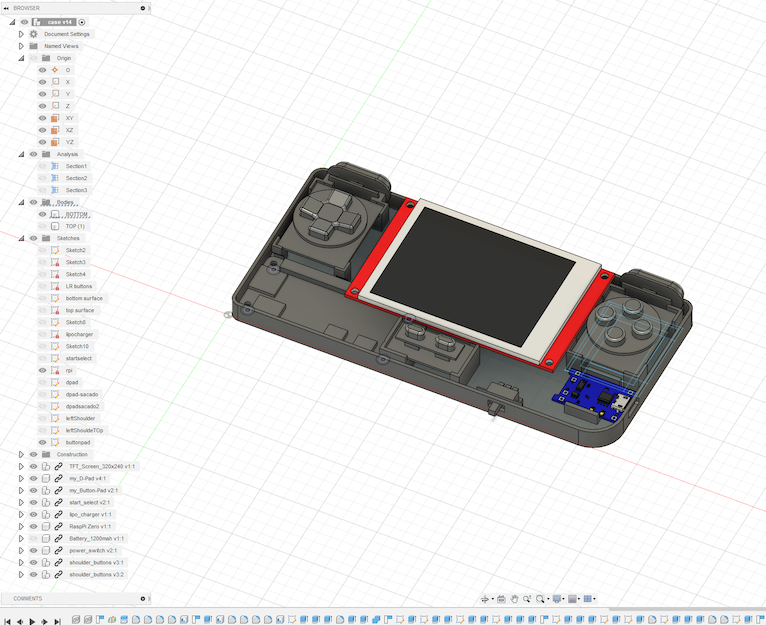
Building my own retro game handheld

So, after going through the thingiverse library looking for cool prints, I thought one of the coolest was Adafruit’s Pi GRRL Zero. I liked the shape, it was compact but big enough to have a confortable grip.

This design was pretty cool but I thought the screen was a little too small, and since the Pi GRRL had a whole guide on how to build the handheld, some assembling videos, and even some software and scripts, I decided to remix the case. It was an excellent reference taking into account my rough experience with electronics.
Prototyping
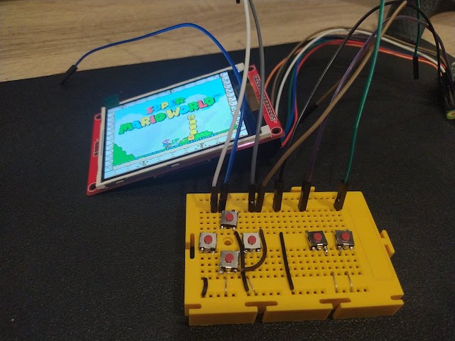
I started by assembing the components in a protoboard, connecting the raspberry and the screen and check configurations. I alse did a fresh installation of RetroPie in my RpiZero.
Screen
The trickiest past here was to wire properly depending on the LCD you have and to compile the right driver. My screen was a 3.5’ LCD like this one. I took the source code for this drivers and change a little bit the intructions for compilation to fit this particular screen. I followed the instructions from this forum just changing the las compilation line to be:
## set driver options
cmake -DSPI_BUS_CLOCK_DIVISOR=6 -DGPIO_TFT_DATA_CONTROL=25 -DGPIO_TFT_RESET_PIN=27 -DGPIO_TFT_BACKLIGHT=18 -DSTATISTICS=0 -DBACKLIGHT_CONTROL=ON -DUSE_DMA_TRANSFERS=OFF -DILI9341=ON
This, plus a “ili9341 wiring pi zero” search on google images gave me a hint on how to wire the screen to the PiZero.
Buttons
For the buttons once again Adafruit and the PiGRRL to the rescue. They have a super easy to install script to configure the GPIO pins to work as buttons, through a configuration file I was able to identify which PIN was used for what button. Just following the steps from Adafruit, as a reminder, PIN and GPIO ports are different things, so it’s nice to have the schematics for the Pi on hand. I left the config file as follow:
# Sample configuration file for retrogame.
# Really minimal syntax, typically two elements per line w/space delimiter:
# 1) a key name (from keyTable.h; shortened from /usr/include/linux/input.h).
# 2) a GPIO pin number; when grounded, will simulate corresponding keypress.
# Uses Broadcom pin numbers for GPIO.
# If first element is GND, the corresponding pin (or pins, multiple can be
# given) is a LOW-level output; an extra ground pin for connecting buttons.
# A '#' character indicates a comment to end-of-line.
# File can be edited "live," no need to restart retrogame!

# Here's a pin configuration for the PiGRRL Zero project:

LEFT        # Joypad left
RIGHT     19  # Joypad right
DOWN      16  # Joypad down
UP        26  # Joypad up
Z         20  # 'A' button
X         21  # 'B' button
#A         16  # 'X' button
#S         19  # 'Y' button
Q         20  # Left shoulder button
W         21  # Right shoulder button
ESC       17  # Exit ROM; PiTFT Button 1
LEFTCTRL  22  # 'Select' button; PiTFT Button 2
ENTER     23  # 'Start' button; PiTFT Button 3
4         27  # PiTFT Button 4

# For configurations with few buttons (e.g. Cupcade), a key can be followed
# by multiple pin numbers.  When those pins are all held for a few seconds,
# this will generate the corresponding keypress (e.g. ESC to exit ROM).
# Only ONE such combo is supported within the file though; later entries
# will override earlier.
You can finde the button installer here: https://learn.adafruit.com/retro-gaming-with-raspberry-pi/adding-controls-software
Battery
For the batery I used a LiPo from AliExpress and also charge controller from the same shop. These were really easy to use and cheap. I have used them in many projects already and worked like a chard, So I just had to fit the controller and the baterry properly in the case.
Example of the battery type: https://es.aliexpress.com/item/4000369075771.html And the USB charge controller: https://es.aliexpress.com/item/4000956074114.html
Case design
Components
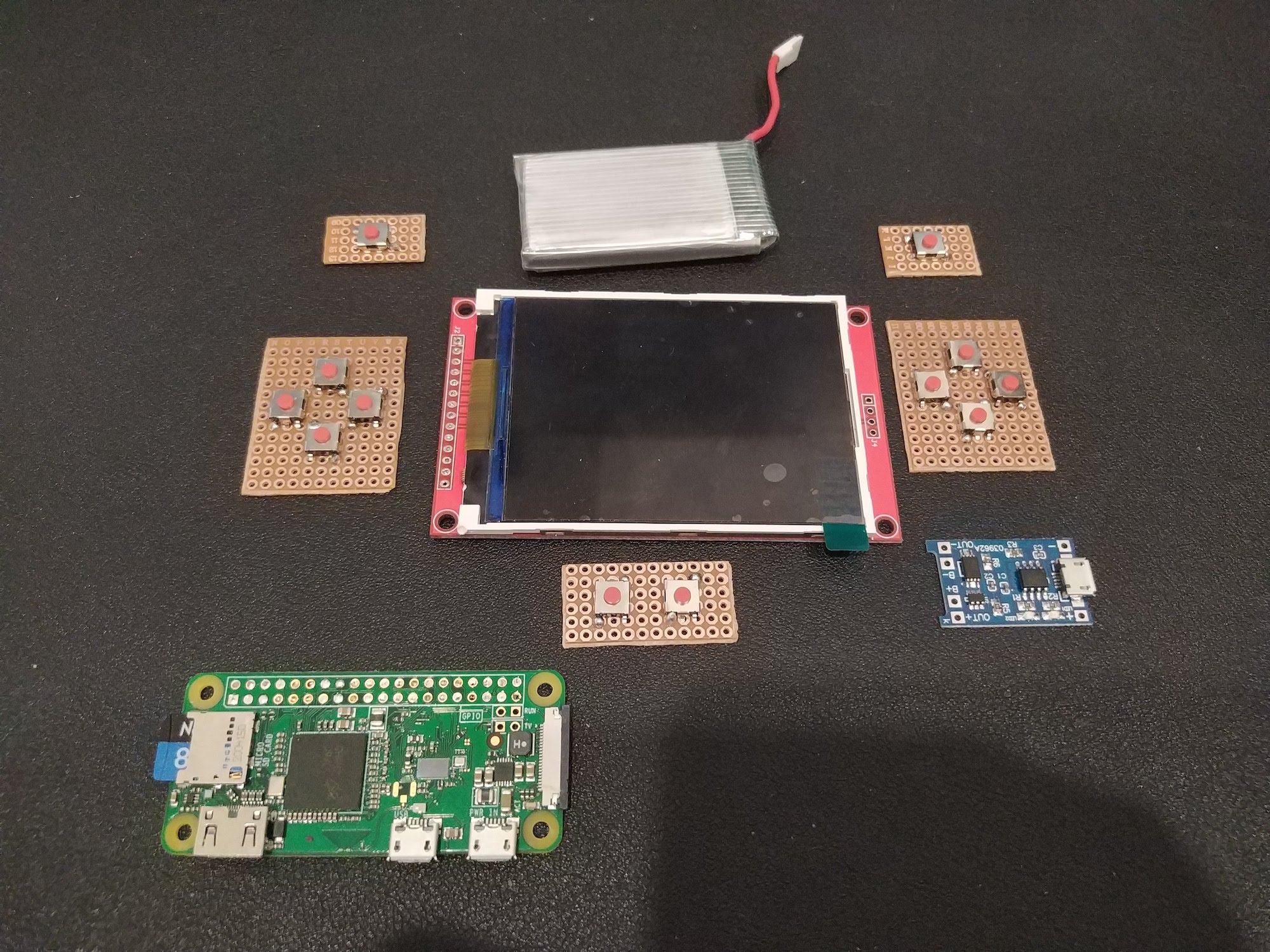
The approach for the case was first to lay all the components I was going to use and model them in the Fusion 360 to have them as reference for the design. I also used GrabCAD to get premodeled components (the Pi the screen, etc)
Model
I followed Noe's PiGRRL tutorial https://www.youtube.com/watch?v=uVGKswaW5OQ but changed the parts that I was interested on changing: Screen size and fitting the components I had. My buttons were solded into proto PCBs that I cut myself. I took several prints to get the right size, and the case has a fundamental flaw. I did not think of the screws, and at the end was only possible to fit two in weird positions, which means the cases does not close correctly. Also, I really wanted the Pi ports available, and that could only be possible by putting it in the corner, where the screw was supposed to go.
An improvement I will consider would be making a snapping case. I did some test but my skills in Fusion 360 were not fit for this task.
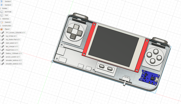
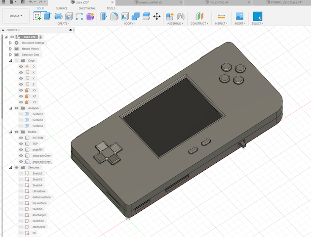
All the STL files can be found in Thingiverse: https://www.thingiverse.com/thing:5385477
Assembling
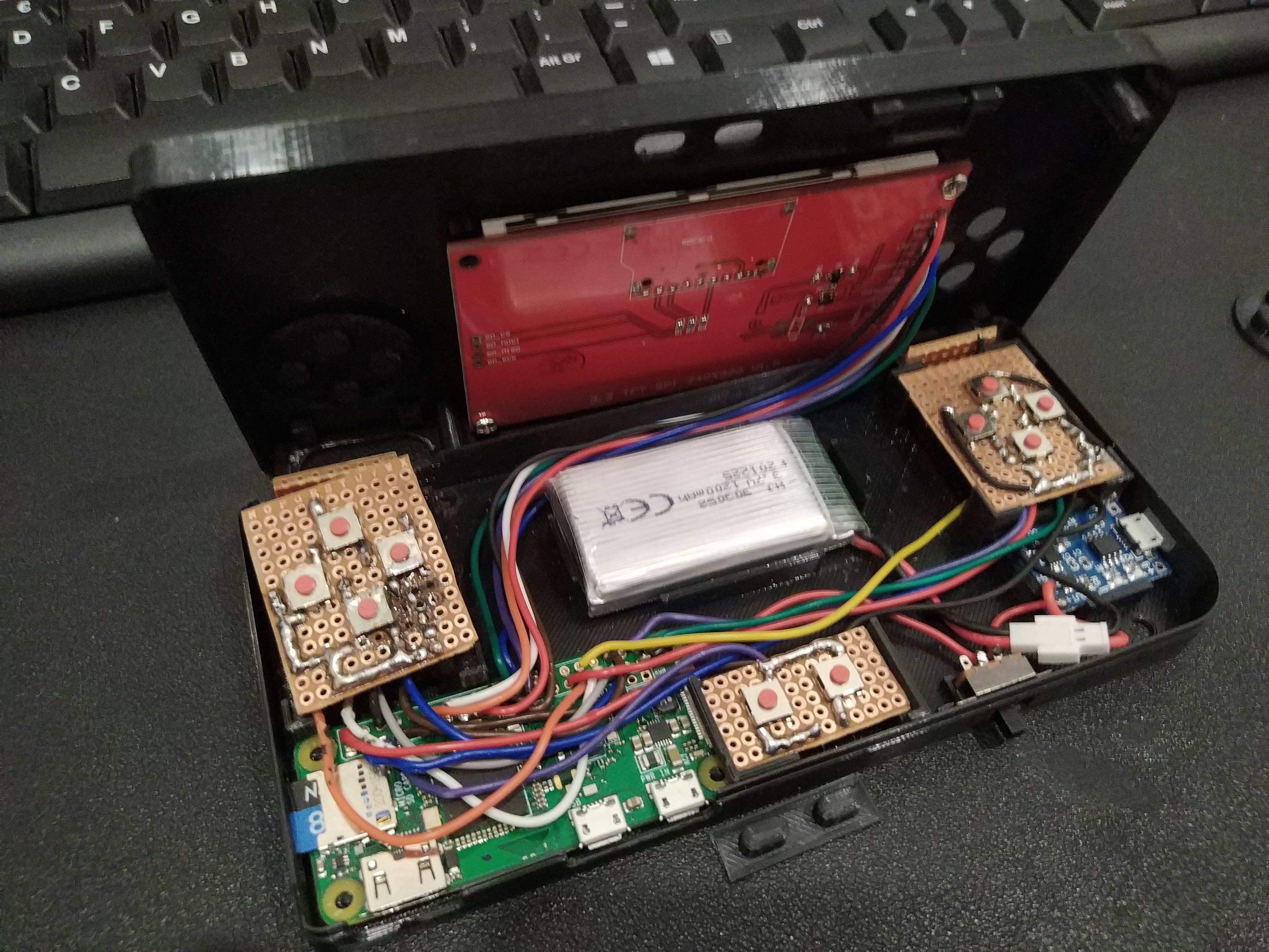
Possibly the most painful part of this project was soldering the cables to the PI, soldering the rest of the cables and then fitting all those cables. Of course designing and using a prefab PCB would have been much easier, but, what’s the fun in that. For closing the case with screen, my printer does not have enough resolution for designing the threads, so Google to the rescue. By heating my M3 screws and then slowly screw them into the plastic, I was able to make them. Now it’s not by all means strong and durable, I had to be very careful when taking them out, not to break them, but it did the trick.
Another assembling issue was that the crews for the TFT were too long, so I had to print some spacers so make them fit.
Play!
Of course as the PiGRRL I installed RetrPie image and a couple of games to test. This was actually the easy part, In the same PiGRRL guide I followed some tips to increase performance. Most games are playable but in some cases I did notice some performance issues. Hopefully in the next iteration of the PiZero I’ll have enough horse power for SNES and Games Boy which at the end of the day are the ones I enjoy the most.
You can see the Pi in action
New case V2 red andsome Zelda testing #3Dprinting #RETROGAMING
— Giuseppe Moretti (@gmoretti) April 3, 2021
:) pic.twitter.com/7AvXvOvjSE
A lot can be improved in this design and the project, but for a first design and prototype I think is more that usable. I hope I return to it sometime in the future.
